Friday, 21 October 2011

Adding Texture

Bump Map


The bump map aims to create a more realistic skin texture to the model. Using my previous UVW map that I created for the skin colouring of my model, I copied this colour map and turned it black and white. I created an even grey tone for the fill colour of a new layer, and then I changed the high pass of the image to 2.1, to create a rough texture for the bump map.


Due to the technical nature of this project it is essential to keep regular back ups of your work. If not, when your main USB device used for storage of files and images of 12 straight hours worth of work decides to corrupt for no specific reason you may find yourself in a bit of a pickle to say the least. If you hadn’t guessed of course this unfortunate event was another part of my journey along this project. I was not amused!


Thank goodness for Auto backup!


I decided that I would take this unfortunate incident and turn it to my advantage and have another go at creating the UVW map, bump map and tweaking the other issues in my project I wasn’t entirely satisfied with to create a better model in the long run.

Some obvious issues with my previous model and uvw map can be seen below in the corner of the eyes and also behind the ear


Do I have something in my eye?


And the ear too...


Unwrap UVW Mapping


It’s all well and good having a head, but a head with no skin? Time to create the skin bitmap that will cover my model and (hopefully) make it look a little less like a Bafta award and more like me!


The process of unwrapping a head and ear


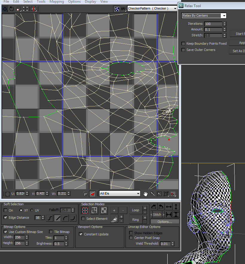
As you can see in these screen grabs I worked my way through creating a UVW map modifier for the head model. Firstly I spread out the face and head, leaving the ear once again as a separate entity. I worked my way through the UVW mapping technique; using a cylindrical selection for the head and selecting the polygons I required using the paint selection tool. I then went about relaxing and spreading out the quads to ensure there were no inverted faces or overlapping edges. This was a relatively simple although time-consuming process. I then went through the same process with the ear, which was a little more difficult due to the complexity of the ear shape.
Eventually I had a UVW map ready for a bitmap skin image to be created upon. 


Normal rendered UVW map

I did check that I had no overlapping or inverted faces although when creating the normal UVW render I saw that I did have a couple that had not previously been picked up. I went back and tried to rectify this although as yet am a little unsure how successful I had been..

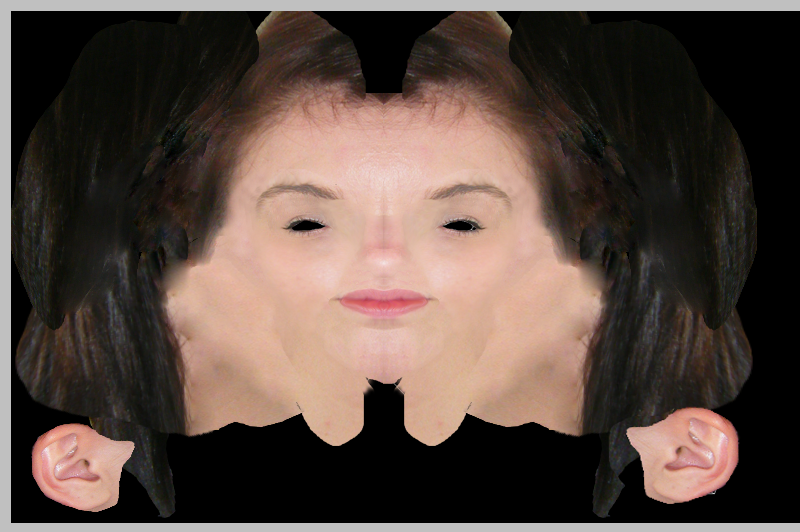
At this point I took the unusual looking net of my face into Photoshop and used quick masking and modifying of borders to create an inverted grid like item that could sit on top of the skin map to ensure everything lined up nicely. Using a cut and paste technique, cutting selections from my original photos and pasting them onto my grid of guidelines I created a rough skin-like appearance. I used the clone stamp and patch functions to reduce the harsh lines created by unmatched skin tones. I also used the hue and saturation modifier to try to match the skin tones a little closer. A function I enjoyed using here and one that I found most useful was the warp tool. It helped me in areas such as my hair region as it was difficult to copy and paste different sections of hair as they differed so much in tone and texture, with the hair falling in different directions and also being different shades of colour entirely. I am not too concerned however with the hair as I hope to create a much more realistic hair texture to go on my model rather than a stretched bitmap across the scalp!


After painting my skin tone onto the UVW map guide, I saved and created a new bitmap material in the material editor and dragged it to my model. The effect was a little disconcerting to say the least! I had hoped that after adding some form of skin texture to the model I could see much better whether it looked how I had imagined… It did not (at least I hope it doesn’t look like me!).


The bitmap was very out of focus and pixilated as you can see in this screen grab. Other little problem areas that required fixing were the eyebrows and lips. For this I used the ‘Liquefy’ modifier in Photoshop and moved some of the pixels around to fit the grid lines more accurately. This did help the look of my model although there is still a way to go to get it looking more realistic!


The Ear


I was dreading the ear slightly. I think perhaps due to the shape and the undulation of the flesh and cartilage in the ear I approached this section of the model with a little trepidation. 


Ear Topology

Similarly to my earlier reference plane images I sectioned the profile image out into blue guidelines, which helped me to carry out the topology. I was very aware of the amount of quads I was creating and tried to limit the amount I drew in order to have a simpler model to work with. Now I’m sure this would have been a good idea had I not started my face model with so many quads as I discovered after transferring my topology covered ear into 3DS Max.

I (using the spline and line technique that I had used for the face), traced my ear topology, attached the polygons, welded the vertices and created an ear model separate from my main head. I then manipulated the vertices to match my reference planes (obviously repositioning and resizing the ear also) and to create the many contour lines an ear has. I was pleased to learn both the chamfer function and the extrude technique to create the ear canal, which I was quite pleased with.

Attaching the Ear

I soon realised that my reference planes did not match up when it came to my ear. My first attempt at positioning the ear ready for reattachment put it somewhere near the back of my head, precariously near my shoulder.


One of the offending ears.


I modified the ear slightly to make it look a little more upright and in the correct position for my head (using the very scientific method of feeling my own head and spending a good deal of time looking in the mirror!).

Once I was satisfied with the position of my lughole, it was time for the surgery of reattachment! That was much easier to type than to actually do. I must have tried about 12 – 15 times to attach my ear to the hole I had left for it although as I mentioned earlier, in my enthusiasm to limit my usage of polygons I had forgotten to factor in requiring a similar amount of vertices on my ear as exists on the face model to match them up successfully. My trusty ‘Cut’ and ‘Create’ tools were required here.


Another issue I came up against was the fiddly process of trying to get close enough to the seam between the ear and the head. After several unsuccessful attempts at an attachment (vertices flying off into the ether thanks to the snaps toggle) I decided upon attaching my ear from a distance and after welding the vertices that were to be attached I brought my ear back in towards the side of my head. This process I found was much easier than trying to guess at which vertex was which and it’s intended partner vertex, although the ‘Weld’ tool was very temperamental. Sometimes it would weld my chosen vertices and at other times decided to have a tea break and not do any welding at all. To overcome this hurdle I did delete a few of my polygons and created some more in their place which seemed to help the welder get back to work. I am still a little unsure why this happened but for now I will set that aside and carry on.


The final ear model


After turbo smoothing

After the successful ear transplant, I used the same technique I used with the lips (holding shift and creating new polygons from existing ones) I created a rough neck and shoulder silhouette that I matched up as best I could to the reference plates that I will manipulate further at a later date. I did this just to ascertain a suggestion of my head being attached to a body of some description.


The Head

The head was adapted from a sphere which I am lead to believe is quite an easy option for creating a head. I did however run into quite a few problems due to my earlier over-exuberance for polygons!


Now on the example tutorial videos I am following it suggests reducing the number of iterations on the sphere to make it easier to work with and to connect to the face model. I was unable to reduce the iterations on the sphere by any more than 1 due to the amount of polygons I had on my face model that were to be connected to the sphere.

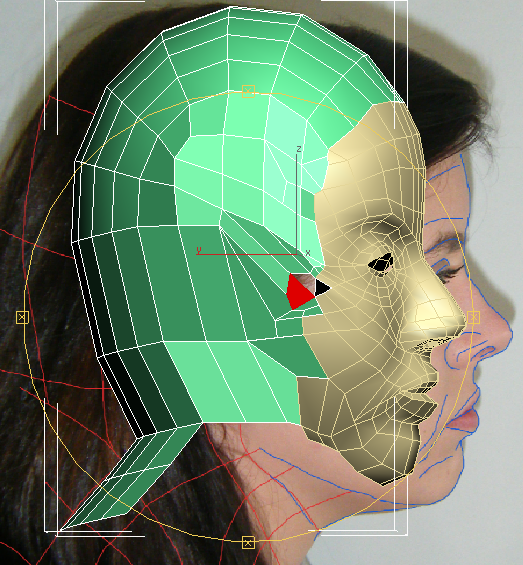
I created a sphere and deleted the polygons I would not need (the front and bottom half of the globe mainly), repositioned and resized the sphere to match my face model. I next set about attaching the vertices around the edge of my face to the edge of the sphere by using the snap toggle to place the vertices in the same position and then using the weld function to secure them to one another.
This worked well for a while until I then came to the temple section near the corner of the eye. Here I did become a little unstuck as I was more than aware of the amount of polygons I had to deal with. I soon found that I had created more than a couple of polygons that had 5 vertices. Some of these I managed to rectify quite quickly using a method I had been shown in the tutorial videos. Others I had to be rather inventive in where I placed the vertices and also I became a bit of a dab hand with the ‘Cut’ tool! This fixed my immediate issue and I was able to connect the face to the sphere successfully.


The head modeling had a few issues regarding the welding as can be seen on the following screen grab, obvious after using the turbosmooth modifier. These were fixed by making sure all of the gaps had been shut by welding the vertices securely. 


I continued to find odd discrepancies with my head model such as a vertex that appeared on the crown of the head for no apparent reason, that was unable to be selected, and turned a quad into a 5 vertex polygon. This I found was due to the symmetry and so I pulled apart the quads from the mirror line and re-positioned back in place, which turned the pentagon back into a friendly quad once again.


Turbo Smoothed Head

My only problem at this point is a fear that I have perhaps given myself a lot more work by yet again increasing my vertex and polygon count significantly. Hey ho, let’s just hope for the best!

The Face


Face

To reduce the amount of polygons on my face I went into edge selection in the edit poly mode and selected edges that weren’t integral to the whole model, ones such as extra polygons on the forehead and cheek areas. I avoided the detailed areas of the nose and eye due to potentially problematic repercussions of my editing. I selected certain edges I was sure wouldn’t cause a problem if they were to be removed, selected ‘ring’ or ‘loop’ depending which contour they followed, which then selected corresponding edges from the same loop and ‘collapsed’ these. This made my model significantly simpler, although ideally if I was creating this model in my own time I think I may have revisited my original topology and started out with a simpler polygon model.

Lips

Creating the lips was pretty straightforward as far as 3D modeling can be as I just selected the edges surrounding the circumference of the mouth (where the lips would connect to the face) and holding down the shift key in select and move I created a new set of polygons that I could then move and manipulate. I did this twice for both the top and bottom lip so that I could create the correct shape for each lip, rounding them into position.


Eyelids

For the eyelids I used the same technique as the lips, holding shift and creating new polygons from the edge of the eyes, ensuring I was lining them up with both the front and profile reference planes.

The only tricky bit that occurred (as happened with the lips also) was connecting the corners, trying not to create an overlap with any of the vertices.


Monday, 17 October 2011

As Promised.. More Manipulation

Let's sort this mess out...

So after a lengthy rearrangement of vertices (I now think I have a few too many vertices! a problem I hope to rectify) this is my eventual 3D object, aligned to my profile image, (see below).


Here are the perspective views, for a better idea.


Ok so although this looks much better and more realistic than it did in my earlier post, it still doesn't really look as good as I had hoped. In the perspective view you can really tell that my cheeks in particular aren't as 'full' and have rather odd looking contours that needed to be sorted out by again going back and rearranging vertices one by one to create a more realistic object.


From 2D to Something Resembling 3D...

Phantom of the Opera?

As continued from my previous post, I started with a flat editable poly of the side of my face that looked like this;


Moving the vertices like this for me was a bit like feeling in the dark. The first column worked well and I lined up all of the vertices onto the edges of my profile image. Moving onto the further columns I found more taxing due to not really knowing for sure where to place the vertices, especially round the more detailed areas such as the eye, nose and lips.


Due to my unsure placement of the vertices, my original manipulations made my face rather elongated and stretched out. I had not accounted for how much of my face could be seen on the front view. I looked at my abnormally stretched object and realised that in the front view I could only actually see to near my cheekbone, whereas I had moved the vertices to include the side of my face up to my ear as you can see below.

It is obvious that my placement of the vertices are too far stretched towards the ear as the eye is completely out of place and nowhere near where it should be! Time for some more manipulation!